NETGEAR is aware of a growing number of phone and online scams. To learn how to stay safe click here.
vlan
40 Topics
management VLAN IP
I have several m4250 switches in two different venues, in a physically (and logically) separate network. The general purpose IT network separates them. The uplinks to the IT network are tagged VLAN ports and everything works fine there. I am running engage on one network and I have onboarded the two switches in the other venue. I'm running into a problem where it seems like the way I set up my management VLAN is causing problems, mainly for IGMP/multicast queriers. I have set up the management VLAN as one of the VLANs with devices and I think that's causing problems. should I have the management VLAN set up as a separate IP space? For example, in venue 1 I have VLANs 30, 33, 34 and in the second venue I have VLAN 35. My management VLAN is 30 in the first venue and the switches all have IPs on that VLAN. Should I change the management VLAN back to VLAN 1? If so, what IP addresses do I give them? If I do that, how will I be able to access the second venue from Engage running in the first venue? Thanks! -Blanton41Views0likes1CommentWAX610-100JPS VLAN設定(Untagged/Tagged)について / VLAN Untagged/Tagged setting on wired port
Japanese --- お世話になっております。 弊社にてNETGEAR WAX610-100JPSの導入を検討しており、ユーザーズマニュアル記載の仕様について1点確認させてください。 構成イメージは以下の通りです。 ・WAX610をブリッジモード(NATモード無効、初期設定のまま)で使用 ・SSID1にVLAN ID 1(初期値)を割り当て ・SSID2に別のVLAN ID(例:VLAN 20)を割り当て ・上位のルーターに1本のLANケーブルで接続し、上位ルーター側でVLANごとにセグメントを分離する構成を想定 質問は以下の通りです。 ユーザーズマニュアル151~152ページに記載の「Untagged VLAN」チェックボックスについて、これは有線(イーサネット)インターフェース全体に対する単一の設定と理解しています。この設定を「Untagged VLAN」(デフォルト、VLAN ID 1)のままにした場合、以下のいずれの動作になりますでしょうか。 (A) ネイティブVLAN(この場合VLAN 1)に属するSSIDのフレームはタグなしで送信され、それ以外のVLAN ID(例:VLAN 20)を割り当てたSSIDのフレームは自動的にタグ付きで同一の有線ポートから同時に送出される(いわゆる802.1Qトランクポートと同様の動作)。 (B) 有線ポートは「タグなしのみ」または「タグ付きのみ」のいずれか一方でしか動作せず、異なるVLAN IDを持つ複数のSSIDのトラフィックを同一の物理ポートで同時に区別して送出することはできない。 (A)の動作であることを確認できれば、1本のLANケーブルでSSID1(VLAN1)とSSID2(VLAN20)の両方のトラフィックを上位ルーターに渡し、上位ルーター側でVLANごとにアクセス制御を行う構成が可能と考えております。マニュアル中にこの点を明記した記載が見当たらなかったため、確認をお願いいたします。 対象製品:WAX610-100JPS 参照箇所:ユーザーズマニュアル 73ページ、85ページ(SSIDごとのVLAN ID設定)、151~152ページ(802.1Q VLANと管理VLANの設定) 以上、よろしくお願いいたします。 English --- Hello, We are considering deploying a NETGEAR WAX610-100JPS, and I would like to confirm one point regarding the specifications described in the User Manual. The intended configuration is as follows: WAX610 used in Bridge mode (NAT mode disabled, default settings) - SSID1 assigned VLAN ID 1 (default) - SSID2 assigned a different VLAN ID (e.g., VLAN 20) - Connected to an upstream router via a single LAN cable, with the upstream router separating segments per VLAN My question is as follows. Regarding the "Untagged VLAN" checkbox described on pages 151-152 of the User Manual, I understand this to be a single setting that applies to the entire wired (Ethernet) interface. If this setting is left as "Untagged VLAN" (default, VLAN ID 1), which of the following behaviors occurs? (A) Frames belonging to the SSID on the native VLAN (VLAN 1 in this case) are sent untagged, while frames from SSIDs assigned other VLAN IDs (e.g., VLAN 20) are automatically tagged and sent out simultaneously from the same wired port (i.e., behavior similar to an 802.1Q trunk port). (B) The wired port operates in only one mode at a time - either "untagged only" or "tagged only" - and cannot simultaneously distinguish and send traffic from multiple SSIDs with different VLAN IDs out of the same physical port. If behavior (A) is confirmed, we believe it would be possible to pass traffic from both SSID1 (VLAN1) and SSID2 (VLAN20) to the upstream router over a single LAN cable, with access control per VLAN handled on the upstream router side. Since we could not find a clear statement on this point in the manual, we would appreciate your confirmation. Target product: WAX610-100JPS Reference: User Manual pages 73 and 85 (VLAN ID setting per SSID), pages 151-152 (802.1Q VLAN and management VLAN settings) Thank you in advance.Solved143Views0likes2CommentsThree GS308E, PFSense, cannot get VLAN working on third switch
I'm working on getting VLAN setup in my home network. All of the switches are GS308E and have the VLAN turned on for the type "Advanced 802.1Q VLAN". The "LAN" coming into Port 1 of Switch 1 is coming from the TPLink Switch that is connected to the PFSense box. Switch 1 with Port 2 connects to Switch 2 with Port 1. The same for Switch 2 Port 2 connects to Switch 3 with Port 1. Eventually Switch 3 with Port 2 will connect to a ReoLink PoE for my Cameras/Frigate setup. On Switch 1: Ports 6, 7, and 8 setup for VLAN 400. Ports 3 setup for VLAN 300. Ports 2 setup to go to Port 1 of Switch 2 Ports 1 setup to connect to the LAN On Switch 2: Port 1 is connected to Switch 1 Port 2 Port 2 is connected to Switch 3 Port 1 No VLAN has been setup at this point on this Switch On Switch 3: Port 1 is connected to Switch 2 Port 2 Port 8 is setup for VLAN 602 For all the Switches I have the VLAN 1 which is the default VLAN. For Switch 1, I'm able to connect my laptop with Ubuntu 24.04 and a Raspberry Pi 5 with Ubuntu 24.04 just fine to Port 6-8. I've tried to connect another computer (Ubuntu 24.04) to Switch 3 Port 8, but it fails to connect. I've taken my laptop and tried, but it also doesn't connect. Now when I connect to like Switch 3 port 6, it connects just fine. I started this post last night, but just finishing it up this morning. I'll dig back into the setup of things and see if I have done something incorrectly. Below is the setup of PFSense and an outline of how I have configured the Switches. If there is something else that I'm not included, please ask for it and I'll see if I can capture it, as I'll be messing around trying to get this to work. I've put in screen shots of the PFSense setup - put in bold of my comments so they stand out... PICS will be done during edits of this post - won't post to start... In Pfsense I can see my three switches (which have not been assigned a static IP at this point) In Pfsense, these are the VLAN setup. These are the Interface Assignments: Here is the Configuration of the SecurityCams2 (VLAN 602) The configuration of the DHCP Servier for VLAN 602 The last part, the Rules for the new VLAN. Switch Configurations =================== Ports-Connections and VLAN assignment ====== Switch 1 Port 1 - Connects to the LAN of the PFSense Box Port 2 - Connects to the Port 1 of Switch TWO Port 6 - VLAN 400 Port 7 - VLAN 400 Port 8 - VLAN 400 Switch 2 Port 1- Connects to LAN of the PFSense box going to Switch 1 port TWO Port 2- Connects to the Port 1 of Switch THREE Switch 3 Port 1 - Connects to LAN of the PFSense box going to Switch 2 port TWO Port 2 - Will connect to another switch, but have not connected at this point. Port8 - VLAN 602 VLANs Definition in Switch 1 --------------------------- VLAN=1 (Default) Port 1 - U Port 2 -U Port 3 - E Port 4- U Port 5- U Port 6- E Port 7- E Port 8- E VLAN=300 Port 1 - T Port 2 -T Port 3 - U Port 4- E Port 5- E Port 6- E Port 7- E Port 8- E VLAN=400 Port 1 - T Port 2 -T Port 3 - E Port 4- E Port 5- E Port 6- U Port 7- U Port 8- U VLANs Definition in Switch 2 --------------------------- VLAN=1 (Default) Port 1 - U Port 2 -U Port 3 - U Port 4- U Port 5- U Port 6- U Port 7- U Port 8- U VLANs Definition in Switch 3 --------------------------- VLAN=1 (Default) Port 1 - U Port 2 -U Port 3 - U Port 4- U Port 5- U Port 6- U Port 7- U Port 8- E VLAN=602 Port 1 - T Port 2 -E Port 3 - E Port 4- E Port 5- E Port 6- E Port 7- E Port 8- U PVID table ========= Switch 1 Port 1 - 1*, 300, 400 Port 2- 1*, 300, 400 Port 3- 300* Port 4- 1* Port 5- 1* Port 6- 400* Port 7 - 400* Port 8 - 400* Switch 2 -------- Port 1 - 1*, 602 Port 2- 1* Port 3- 1* Port 4- 1* Port 5- 1* Port 6- 1* Port 7 - 1* Port 8 - 602* Switch 3 Port 1 - 1*, 602 Port 2- 1* Port 3- 1* Port 4- 1* Port 5- 1* Port 6- 1* Port 7 - 1* Port 8 - 602*GS308Ev4, GS305E - Help with uplinks/downlinks
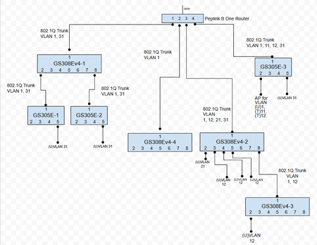
Could I please have some help or confirmation that I have these setup correctly? I'm weary that they are because I sometimes have trouble connecting to the admin interfaces on these switches. I've already locked myself out of about 5 of these (they become unreachable) and had to do factory resets and start over. Other times, I login and the admin pages don't fully load. Or sometimes they load with weird names and labels. Sometimes I logout and chrome says "no data from site". I'm concerned I'm losing some packets somewhere. But generally speaking, everything is working and the untagged (U) vlan access ports are divvying out the correct ip addresses and devices are communicating within themselves ok. I don't think I'm understanding how the uplinks/downlinks need to be tagged, or untagged. Here's the big picture. Looking at it on paper makes me feel like I'm way out of league. There's a lot of empty ports, I'm just starting. Here's the 4 port setup on the router Let me just start down the port 1 trunk (stuff on left of picture). Here's the setup of GS308Ev4-1 for VLAN1 Same router VLAN31 Same router pvid And then both GS305E-1 and -2 are setup the same which is: How am I doing?748Views0likes18CommentsM4300 routing table Next Hop is Mgmt IP
Apologies for the dumb question: I have two M4300's stacked together with three VLANs configured. VLAN 10 has range 10.0.10.0/24, the gateway is (supposed to be) 10.0.10.1 and the management interface is at 10.0.10.252. However, the routing table for 10.0.10.0 shows the next hop as 10.0.10.252 which must have been set when I chose that IP for the management interface. I was expecting it to be the gateway not the management interface? In "IPv4 Management VLAN Configuration", The management VLAN is 10, Routing Mode is enabled, the IP Address/Subnet Mask are as above and the Gateway is 10.0.10.1. I can ping devices on VLAN10 including the management interface, but not the Gateway. Neither can I ping anything on the other VLANs. Is this normal or have I messed up my config somehow?194Views0likes2CommentsVLAN
Hi an alle, ich habe einen GS752TXPv3 Switch und würde gerne ein VLAN 50 untagged erstellen 192.168.50.0/255.255.255.0 im VLAN1 - 192.168.1.0/255.255.255.0 läuft ein DHCP Server für VLAN1 u. VLAN50 Wie muss ich das VLAN50 am Switch konfigurieren das der DHCP relay zu diesem DHCP funktioniert ? Wie bekomme ich ein Routing von VLAN50 zu VLAN1 konfiguriert ?GS1xxE and their PoE equivalents. Getting them an IP using DHCP on a specific vlan.
Hello to anyone taking the time to read this. I have close to a dozen netgear GS1xxE switches at my home and various family member's homes by now and swear by the things. Vlan tagging is a must for our various setups and these switches haven't disapointed yet. However , when it comes to configuring them, the fact one is incapable of selecting the vlan on which the things do their DHCP negotiating forces me to use fixed IP's. In essence this isn't all that bad. But adding this to the firmware isn't something unreasonable to ask I would think. http://i.imgur.com/JZEvBx4.png http://i.imgur.com/p9evrYY.png Thanks in advance for taking the time to reply. If you also think this slight oversight should be rectified please do reply.71KViews21likes16Comments
vlan (ipv6 futureproofing)
Hi, We have a SRX5308 and a couple of FVS336 as well as a few other routers. We are futureproofing our corporate network by deploying ipv6 in parallel of ipv4. our address scheme was chosen as to be as simple for the admins as possible : ipv4 : 10.bbb.ccc.ddd (where bbb also denotes the vlan) ipv6 : fdgg:gggg:gggg:bbb::ccc:ddd:1 it's been deployed within the network, and it runs fine, no issues. our primary firewall-routerchain (not netgear) is also updated and works. I'm now trying to configure one of the netgear, and I'm discovering the issue where the ipv6 mode doesn't support vlan (at least through the GUI). is there any way to actually make ot work (telnet ?) or am I wasting my time, and should at some point replace them with other hardware ?15KViews3likes1CommentHowto change management vlanid on gs724T
Hi Everyone, I have a Prosafe XS716T here where I need to change management VLAN to 12 instead of 1. I've read that changing is possible and has solved some cases of networking but I haven't really found the option in my web interface. Maybe you can point in the right direction for that? Thanks a lot, I appreciate all the help I can get.SolvedIP ACL Vlans MG5300
Hello, I would like to implement IPv4 ACL policies in a Vlan segmentated network. My core switch is an M5300-28G ProSafe 24-port Gigabit L2+ with 10 Gigabit Stacking, 10.0.0.44, B1.0.0.5. I have the following vlan on the MG5300: Vlan1 192.168.0.0/24 - Servers + Internet Gateway Vlan10 192.168.10.0/24 Vlan20 192.168.20.0/24 Vlan30 192.168.30.0/24 Vlan40 192.168.40.0/24 Vlan50 192.168.50.0/24 Vlan60 192.168.60.0/24 Vlan70 192.168.70.0/24 - Printers I need to implement: Vlan10 Acces to vlan1 (to permit access to Servers and Internet) Access to Vlan70 (to permit access to printers) No Access to Vlan20, vlan30, vlan40, vlan50, vlan60 Vlan20 Acces to vlan1 (to permit access to Servers and Internet) Access to Vlan70 (to permit access to printers) No Access to Vlan10, vlan30, vlan40, vlan50, vlan60 Vlan30 Acces to vlan1 (to permit access to Servers and Internet) Access to Vlan70 (to permit access to printers) No Access to Vlan20, vlan10, vlan40, vlan50, vlan60 Vlan40 Acces to vlan1 (to permit access to Servers and Internet) Access to Vlan70 (to permit access to printers) No Access to Vlan20, vlan30, vlan10, vlan50, vlan60 Vlan50 Acces to vlan1 (to permit access to Servers and Internet) Access to Vlan70 (to permit access to printers) No Access to Vlan20, vlan30, vlan40, vlan10, vlan60 Vlan60 Acces to vlan1 (to permit access to Servers and Internet) Access to Vlan70 (to permit access to printers) No Access to Vlan20, vlan30, vlan40, vlan50, vlan10 Which is the best way to implement this requirements ? Thanks so much !2.1KViews0likes3Comments